
The Wall.
PROJECT 02 / 17
SHEETS 06–09
An independent element and a wall come together through a series of model studies, spatial tests, and final drawings.
Architectural summary
The Wall explores how a small assembly of planes and slender members can connect to two intersecting walls. Physical models test different arrangements before placement sketches compare positions around the corner. The final model and drawings show rectangular openings, projecting ledges, and a central volume, making the relationships between solid surfaces and open space easier to read.
Wall Composition
PORTFOLIO SHEET 06Wall and Element Assembly
The physical model brings two intersecting walls together with rectangular openings, projecting ledges, and a central volume that overlaps the surrounding frames.
Original sheet & annotations +
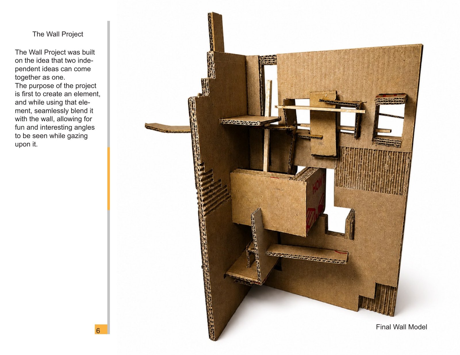
The Wall: wall composition. This presentation sheet brings together wall and element assembly, preserving the original layout and annotations.
Element Study Models
PORTFOLIO SHEET 07Three Element Model Studies
Three small physical models arrange flat pieces and slender members in different ways, comparing open frames, angled surfaces, and projecting edges.
Study Models from Another Angle
This alternate view of the three physical models shows upright planes, narrow connections, and open gaps that are less visible from the first angle.
Intersecting Planes and Members
A close view of one physical model shows flat planes crossed by slender members, with long projections extending in several directions from the center.
Original sheet & annotations +
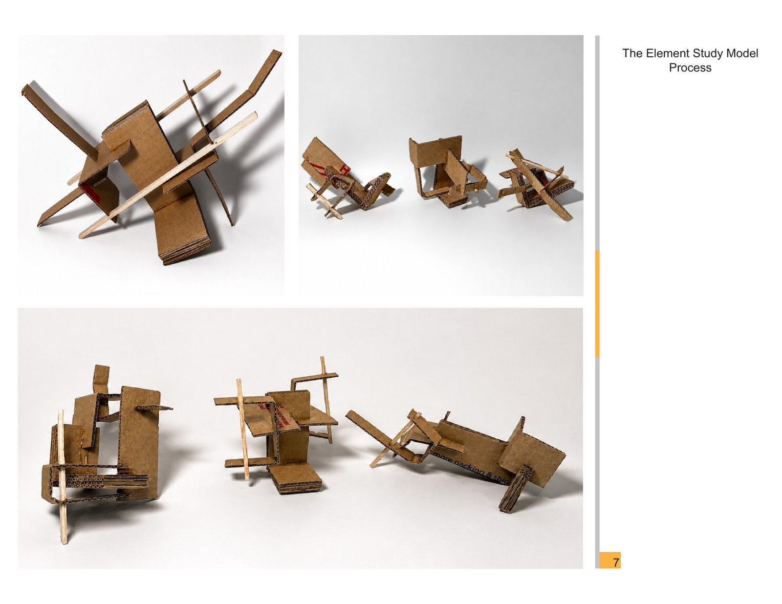
The Wall: element study models. This presentation sheet brings together three element model studies, study models from another angle, intersecting planes and members, preserving the original layout and annotations.
Combining Wall & Element
PORTFOLIO SHEET 08Plan of Wall and Element
The plan drawing shows an L-shaped wall intersecting a group of rectangular elements, using solid and dashed lines to distinguish visible and hidden edges.
Element Crossing the Wall
An annotated placement sketch positions the element across one wall near the corner, with arrows identifying the layered pieces and connecting dowels.
Element Along the Wall
This placement sketch arranges most of the element along one side of the L-shaped wall, with smaller pieces projecting through to the opposite side.
Element at the Corner
This annotated sketch positions the element directly around the inside corner, showing how its parts overlap the two legs of the wall.
Original sheet & annotations +
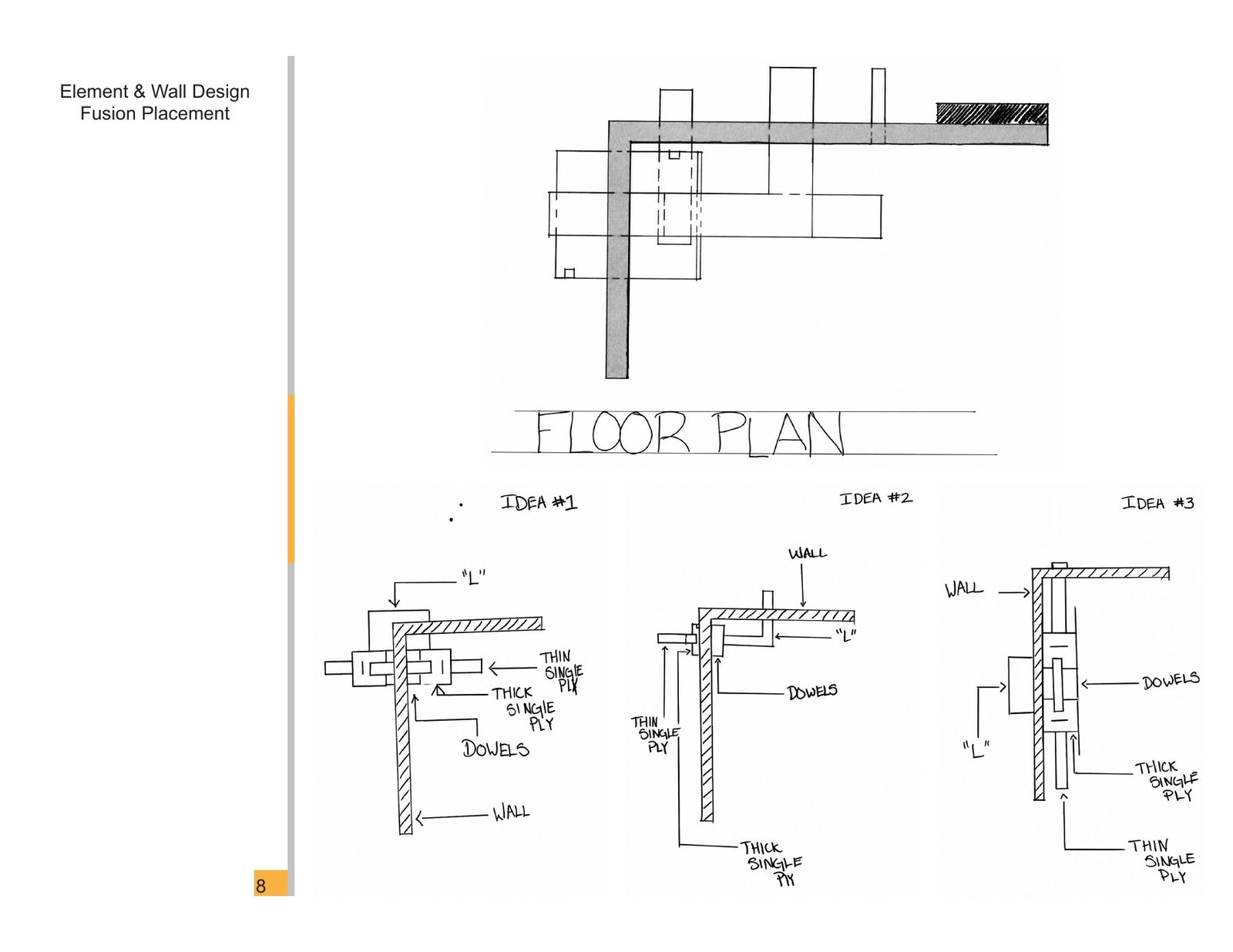
The Wall: combining wall & element. This presentation sheet brings together plan of wall and element, element crossing the wall, element along the wall and related views, preserving the original layout and annotations.
Final Model & Drawings
PORTFOLIO SHEET 09Large Wall Cut Drawing
A line drawing shows the broad wall face, rectangular openings, and projecting elements, with dashed outlines indicating parts located behind the visible surface.
Final Assembly Isometric Drawing
The isometric drawing shows how two walls, projecting ledges, and an open central volume fit together, making their overlaps and openings visible at once.
Front Section Through Assembly
The front section records the stepped wall profile, central opening, and projecting members above a hatched base, with dashed lines marking hidden edges.
Narrow Wall Cut Drawing
This drawing records the narrower wall face, showing its stepped outline, rectangular opening, and projecting members alongside dashed outlines of the elements behind it.
Original sheet & annotations +
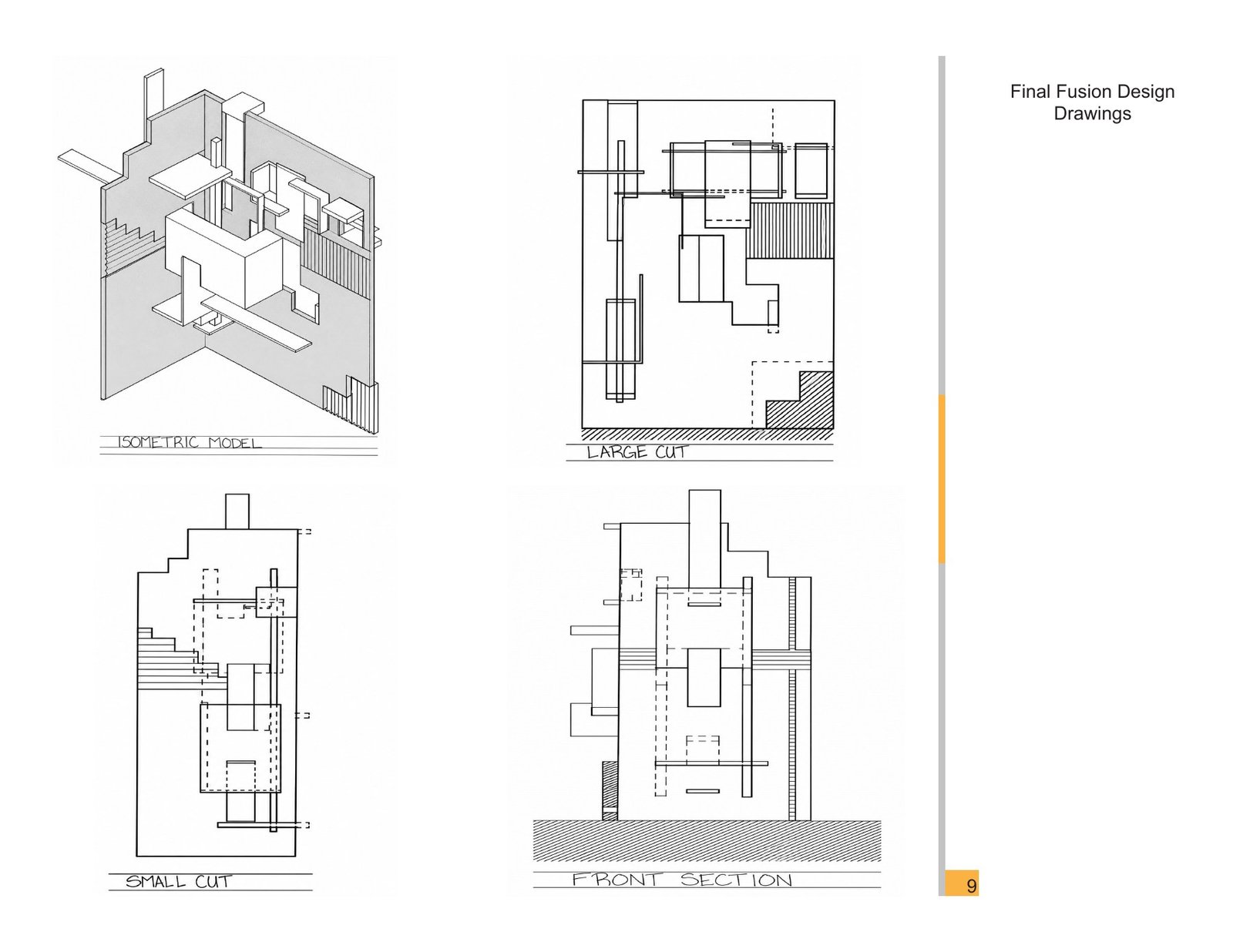
The Wall: final model & drawings. This presentation sheet brings together large wall cut drawing, final assembly isometric drawing, front section through assembly and related views, preserving the original layout and annotations.